DIY Optical Sensor help

ellisz

Active Member
View Badges
Joined
Jan 5, 2017
Messages
100
Reaction score
18
Location
S. Indiana
Rating - 0%
0   0   0
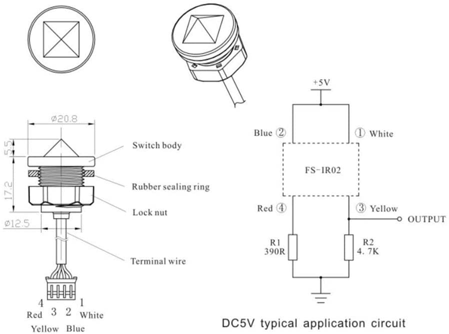
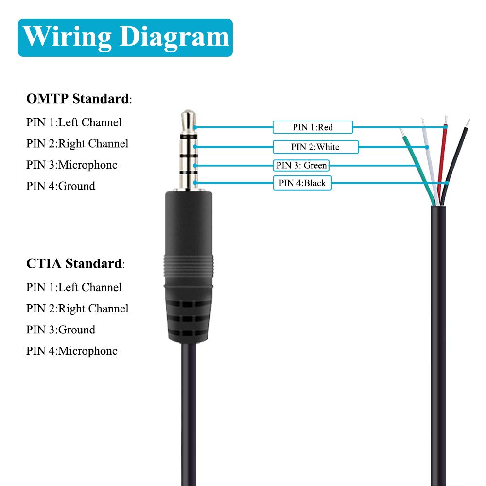
I have been trying to DIY an optical sensor for my FMMs. I have the sensor and the TRRS jack and trying to test the wire configuration. I have been able to get the sensor to open and close but not consistently. The sensor identifies the wire config - Blue & White is +5v. Red & Yellow output/sensor. The TRRS jack has red(tip), white, green, and black(base). I am seeing 4.67v from the Black and Green as well as Red and Green off the jack when plugged into the FMM. Any help as to what wire goes where? I have tested with different configurations but can't seem to get a consistent switching with the sensor.

Optical sensors - Amazon product

TRRS jack - Amazon product

Any words of wisdom or is this a fools errand? I have some Neptune optical sensors in use as well but thought I would do a little DIY for back ups.

Thanks
 

WVNed

The fish are staring at me with hungry eyes.
View Badges
Joined
Apr 11, 2018
Messages
10,206
Reaction score
39,476
Location
Hurricane, WV
Rating - 0%
0   0   0
Do understand how it works and are wiring diagrams meaningful to you?

This is what I found

The sensor has 2 circuits
One lights a LED
The other has a phototransistor the sees the light from the LED based on how it refracts. Since it refracts differently when wet and dry that is how it senses a water level.

R1 is a current limiting resistor for a LED
R2 is a pull down resistor so the output goes to 0 if the sensor is off. It goes to 5v when the transistor is on
R1 & R2 should be inside the FMM and not the sensor. So is the output.

SO what you are working with are the 4 wires at the point where the circled numbers 1 to 4 are on the diagram.


The sensors are colored differently but have the same functions


51onINEu8AL._AC_SL1000_.jpg

images


The Neptune end
image-jpg.652599

Then you need to wire the optical sensor into the male connector with the proper pinout. Here is the pinout of the neptune optical sensor:

Pin one (closest to base of plug) Red
Pin two Green
Pin three Black
Pin four White

The generic optical sensors will probably have different colors on them, but generally Green is the Blue wire, and the Black is the Yellow


I hope this helps and is not just enough to be dangerous.
 
OP
OP
ellisz

ellisz

Active Member
View Badges
Joined
Jan 5, 2017
Messages
100
Reaction score
18
Location
S. Indiana
Rating - 0%
0   0   0
I know enough to be dangerous - I think. I was pretty sure it was really just getting the the 4 wires from the sensor connected to the 4 wires on the jack in the right order. Expected it to be easier than it turned out. I am testing by putting the sensor in water and watching for it to open on the dashboard(not Fusion). The Neptune sensor works as expected.

Let me double check my connections and see if I missed something. Thanks for the detail.
 
OP
OP
ellisz

ellisz

Active Member
View Badges
Joined
Jan 5, 2017
Messages
100
Reaction score
18
Location
S. Indiana
Rating - 0%
0   0   0
Went and tested again. I put white to white, red to red, yellow to black, and blue to green.

This gives me a closed switch no matter what. If I swap the black and green, I get an open switch all of the time.
 

WVNed

The fish are staring at me with hungry eyes.
View Badges
Joined
Apr 11, 2018
Messages
10,206
Reaction score
39,476
Location
Hurricane, WV
Rating - 0%
0   0   0
Look into this. Ignore the colors. There is no standard. Pay attention to what color comes out where on each end

61kWZruOMhL._SL1000_.jpg
image-jpg.652599


so
Tip - Red on plug to white on sensor
Ring 1 - White on plug to yellow on sensor
Ring 2 - Green on plug to blue on sensor
Ring 3 - Black on plug to red on sensor

With one of the pigtails plugged in you should see 5 volts more or less green to black and red to white
 
Last edited:
OP
OP
ellisz

ellisz

Active Member
View Badges
Joined
Jan 5, 2017
Messages
100
Reaction score
18
Location
S. Indiana
Rating - 0%
0   0   0
Thanks for calling out captain obvious! Sorry I took things a little too literal. I got one soldered up and working. Just have to figure out how I want to lay out the FMM's.

Thanks for all of the help.
 

bozo

Well-Known Member
View Badges
Joined
Nov 19, 2015
Messages
522
Reaction score
150
Rating - 100%
2   0   0
also wondering which combination ended up working for you

I just wired these up.


You have to use the connectivity option on the multimeter to test which color wire goes to which TRRS pin.

Once you match the color of the wires to the pin number, you can solder your wires to the optical switch wires

You also have to ask the vendor who you bought the optical sensor from for a wire color diagram.

For me (could be different colors for you):

Pin 1 on the TRRS jack (Green Wire) -> Solders to Red Wire on the Optical Sensor

Pin 2 on the TRRS jack (Yellow Wire ) -> Solders to Blue Wire on the Optical Sensor

Pin 3 on the TRRS jack (Red Wire ) -> Solders to Yellow Wire on the Optical Sensor

Pin 4 on the TRRS jack (wHITE Wire ) -> Solders to White Wire on the Optical Sensor
 

Randyp79

Well-Known Member
View Badges
Joined
Sep 11, 2014
Messages
555
Reaction score
317
Rating - 0%
0   0   0
Just ordered this guy on Amazon and soldered it up to existing Neptune optical sensor jack.

White to white
Red to red
Yellow to black
Green to blue

Works perfectly.
 

Attachments

  • Screenshot_20240206_180741_Amazon Shopping.jpg
    Screenshot_20240206_180741_Amazon Shopping.jpg
    84.1 KB · Views: 176

Mmoore0324

Community Member
View Badges
Joined
Mar 28, 2012
Messages
90
Reaction score
58
Location
Cape Coral,fl
Rating - 0%
0   0   0
Look into this. Ignore the colors. There is no standard. Pay attention to what color comes out where on each end

61kWZruOMhL._SL1000_.jpg
image-jpg.652599


so
Tip - Red on plug to white on sensor
Ring 1 - White on plug to yellow on sensor
Ring 2 - Green on plug to blue on sensor
Ring 3 - Black on plug to red on sensor

With one of the pigtails plugged in you should see 5 volts more or less green to black and red to white
I know this is an old thread, but I have that same 3.5mm cord and the same sensor from Amazon. I can not get it to work no matter the combo that I try. I suppose I could have a bad sensor. I have a new one coming Friday that I'll test this combo again. I'm getting 5v from the tip (left channel) on the plug I'd assume that go to the blue wire on the sensor which should be VCC? And then white on the plug (R channel) to white on the sensor (output signal).
 

TOP 10 Trending Threads

HOW DO YOU ADJUST YOUR CUC AS ALGAE DISAPPEARS?

  • Capture and re-home CUC

    Votes: 6 6.5%
  • Increase white light/hours in tank to spur algae growth to feed CUC

    Votes: 6 6.5%
  • Feed nori to support CUC

    Votes: 31 33.7%
  • Feed herbivore pellets to support CUC

    Votes: 30 32.6%
  • Allow attrition to balance CUC and algae

    Votes: 40 43.5%
  • Provide macro algae to feed CUC

    Votes: 6 6.5%
  • Introduce CUC predators

    Votes: 1 1.1%
  • Other (please explain)

    Votes: 9 9.8%
Back
Top