Reefpi pca9685 driver issue

Lokilow

New Member
View Badges
Joined
Mar 3, 2021
Messages
14
Reaction score
8
Location
Colorado
Rating - 0%
0   0   0
Hi guys, i couldn't find any solutions searching online and reading around.

I'm a fresh water guy so I'm really only trying my hand at pwm control using a pca9685 driver but i can't select the driver or create a driver in reefpi.

So I've been going through the tutorials on adafruit about setup and test. Normal pwm using raspberry pi works fine, in the first tutorial. Jumping to the lighting tutorial once it comes to making a new jack i am unable to select any driver besides raspberry pi. I then go to configuration to check drivers and it only shows raspberry pi, trying to create a pca driver i get an "failed to create: error remote i/o 500" message.

I started with reefpi version 3 but updated to version 4 to see if that was the issue. I am using a pi zero w.
Any ideas what's up?
 

robsworld78

Well-Known Member
View Badges
Joined
Feb 14, 2020
Messages
952
Reaction score
1,281
Location
Edmonton, Canada
Rating - 0%
0   0   0
Hi guys, i couldn't find any solutions searching online and reading around.

I'm a fresh water guy so I'm really only trying my hand at pwm control using a pca9685 driver but i can't select the driver or create a driver in reefpi.

So I've been going through the tutorials on adafruit about setup and test. Normal pwm using raspberry pi works fine, in the first tutorial. Jumping to the lighting tutorial once it comes to making a new jack i am unable to select any driver besides raspberry pi. I then go to configuration to check drivers and it only shows raspberry pi, trying to create a pca driver i get an "failed to create: error remote i/o 500" message.

I started with reefpi version 3 but updated to version 4 to see if that was the issue. I am using a pi zero w.
Any ideas what's up?
Hi, have you enabled I2C on the Pi? Can you run the following command in the Pi terminal window, this will tell us if the hardware is ok.

i2cdetect -y 1

You should get a list with 40 and 70.
 
OP
OP
L

Lokilow

New Member
View Badges
Joined
Mar 3, 2021
Messages
14
Reaction score
8
Location
Colorado
Rating - 0%
0   0   0
Hi, have you enabled I2C on the Pi? Can you run the following command in the Pi terminal window, this will tell us if the hardware is ok.

i2cdetect -y 1

You should get a list with 40 and 70.
Yes it is enabled. And SPI is disabled. I have also toggled these on and off more than once to see if it took. Also verified by doing it in the terminal and gui.
 

robsworld78

Well-Known Member
View Badges
Joined
Feb 14, 2020
Messages
952
Reaction score
1,281
Location
Edmonton, Canada
Rating - 0%
0   0   0
Yes it is enabled. And SPI is disabled. I have also toggled these on and off more than once to see if it took. Also verified by doing it in the terminal and gui.
Do you see address 40 with i2cdetect? That would be 64 in reef-pi.
 
OP
OP
L

Lokilow

New Member
View Badges
Joined
Mar 3, 2021
Messages
14
Reaction score
8
Location
Colorado
Rating - 0%
0   0   0
So i don't have the actual driver plugged into since I'm dry testing however when i do the command you said i get a grid.
The rows are 0123456789abcdef
And the columns are 00-70
Inside is understandably blank.
When i plug the board in i do get 40 and 70 inside the grid.
So..... Turns out i had the dang driver wired wrong at first so pi didn't actually see it and the driver couldn't be made. This seems like an oversight, i would think one should be able to setup the software side before having everything wired in.

But I'm any case with your help we got it figured out for now! Thank you.
 

robsworld78

Well-Known Member
View Badges
Joined
Feb 14, 2020
Messages
952
Reaction score
1,281
Location
Edmonton, Canada
Rating - 0%
0   0   0
So i don't have the actual driver plugged into since I'm dry testing however when i do the command you said i get a grid.
The rows are 0123456789abcdef
And the columns are 00-70
Inside is understandably blank.
When i plug the board in i do get 40 and 70 inside the grid.
So..... Turns out i had the dang driver wired wrong at first so pi didn't actually see it and the driver couldn't be made. This seems like an oversight, i would think one should be able to setup the software side before having everything wired in.

But I'm any case with your help we got it figured out for now! Thank you.
Right on, glad you got it working.
 
OP
OP
L

Lokilow

New Member
View Badges
Joined
Mar 3, 2021
Messages
14
Reaction score
8
Location
Colorado
Rating - 0%
0   0   0
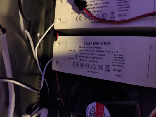
Here's a fun one, trying to control 4 sperate led drivers that are all independent and so none of them share the same ground as the pi. I'm searching how to do this but anyone have an idea in the mean time?
Attached is the drivers I'll be controlling, they have their own pwm lines which work great when attached to pots.
 

Attachments

  • P_20210307_201012.jpg
    P_20210307_201012.jpg
    96.3 KB · Views: 49

robsworld78

Well-Known Member
View Badges
Joined
Feb 14, 2020
Messages
952
Reaction score
1,281
Location
Edmonton, Canada
Rating - 0%
0   0   0
Here's a fun one, trying to control 4 sperate led drivers that are all independent and so none of them share the same ground as the pi. I'm searching how to do this but anyone have an idea in the mean time?
Attached is the drivers I'll be controlling, they have their own pwm lines which work great when attached to pots.
You need to connect the GND to a common ground on Pi. Without that they won't dim.
 
OP
OP
L

Lokilow

New Member
View Badges
Joined
Mar 3, 2021
Messages
14
Reaction score
8
Location
Colorado
Rating - 0%
0   0   0
I understand that, was wondering if there was anything I was missing like a type of driver or controller.

Im going to try to power all of the drivers with the same powerline from one driver. I also need to make sure the power ground is the same as the output ground or else that wouldnt work. If the output grounds are different than the input then I dont know how I can use one PI to control all of them. As I believe simply "tying" all the output grounds together wouldnt work either. Ill post after some more testing.
 

robsworld78

Well-Known Member
View Badges
Joined
Feb 14, 2020
Messages
952
Reaction score
1,281
Location
Edmonton, Canada
Rating - 0%
0   0   0
I understand that, was wondering if there was anything I was missing like a type of driver or controller.

Im going to try to power all of the drivers with the same powerline from one driver. I also need to make sure the power ground is the same as the output ground or else that wouldnt work. If the output grounds are different than the input then I dont know how I can use one PI to control all of them. As I believe simply "tying" all the output grounds together wouldnt work either. Ill post after some more testing.
As long as you're using a PWM pin from pca9685 it should work. When you add the Jack connector select the pca9685 driver you added and the pin number you use. Then you can access on the light tab. That's all you should need in reef-pi.

Those drivers are AC so tie all the inputs in parallel to your main line. For dimming connect all the Black:GND wires together and connect to a GND pin on Pi, then run a signal wire from pca9685 to each PWM on driver.
 
OP
OP
L

Lokilow

New Member
View Badges
Joined
Mar 3, 2021
Messages
14
Reaction score
8
Location
Colorado
Rating - 0%
0   0   0
So that's what i thought at first to, thinking it should be super simple. When i was testing it out the driver was pwm'ing' fine with one led but giving 0v when i connected the pins for the light.

This caused me to dive straight into over thinking how everything is configured, etc. I've actually designed and build my own LED drivers and learned that led gnds and power gnd sometimes have to be sperate. (for example an al8805 driver).

Turns out I'm just to swamped with projects right now and ONCE again had my pins wrong. I apologise for posting two issues that were both my fault. Esp since I'm actually supposed to be a electrical engineer in profession! Jeez

Thanks for the help and patience Rob.
 

SoundsDigital

New Member
View Badges
Joined
May 2, 2022
Messages
13
Reaction score
7
Location
Cardiff
Rating - 0%
0   0   0
I'm having an issue with PWM too. When I type i2Cdetect I get the following

Any ideas what the issue is?

reefpi@reefpi:~ $ i2cdetect -y -l
i2c-1 i2c bcm2835 (i2c@7e804000) I2C adapter
i2c-2 i2c bcm2835 (i2c@7e805000) I2C adapter
 

robsworld78

Well-Known Member
View Badges
Joined
Feb 14, 2020
Messages
952
Reaction score
1,281
Location
Edmonton, Canada
Rating - 0%
0   0   0
I'm having an issue with PWM too. When I type i2Cdetect I get the following

Any ideas what the issue is?

reefpi@reefpi:~ $ i2cdetect -y -l
i2c-1 i2c bcm2835 (i2c@7e804000) I2C adapter
i2c-2 i2c bcm2835 (i2c@7e805000) I2C adapter
It looks like you have the command wrong at the last character, that should be 1 (one).

i2cdetect -y 1
 

SoundsDigital

New Member
View Badges
Joined
May 2, 2022
Messages
13
Reaction score
7
Location
Cardiff
Rating - 0%
0   0   0
It looks like you have the command wrong at the last character, that should be 1 (one).

i2cdetect -y 1
Finally got it sort of working using a mosfet. Lights now ramping up and down, but every few seconds they flash of and on for a few milliseconds. Guessing this is something to do with the PWM frequency. Tried altering it and it's gone from a few seconds on and a few seconds off to a few milliseconds off after every few seconds. Can't eliminate it completely though.

Any suggestions on a suitable frequency?
 

robsworld78

Well-Known Member
View Badges
Joined
Feb 14, 2020
Messages
952
Reaction score
1,281
Location
Edmonton, Canada
Rating - 0%
0   0   0
Finally got it sort of working using a mosfet. Lights now ramping up and down, but every few seconds they flash of and on for a few milliseconds. Guessing this is something to do with the PWM frequency. Tried altering it and it's gone from a few seconds on and a few seconds off to a few milliseconds off after every few seconds. Can't eliminate it completely though.

Any suggestions on a suitable frequency?
Hmm, not sure, do you have a pulldown resistor on the signal? 4.7k to 10k might eliminate it.
 

SoundsDigital

New Member
View Badges
Joined
May 2, 2022
Messages
13
Reaction score
7
Location
Cardiff
Rating - 0%
0   0   0
Turned out to be a configuration issue. Had my ATO set to the same output pinas the main relay for the lights, though hadn't connected it up. Every time it was checking the ATO level it would turn off the lighting pin.

Unfortunately, my lights contain a blue and a white, but they have a common ground, so need to use relays to switch between blue and white on the positive rail and then use a mosfet to regulate the brightness.

I am tempted to ditch the blue altogether though and just ramp up the lights from about 10 and then at night drop them to about 10 then just switch the blue light on at night, running at 10 all night.
 

Being sticky and staying connected: Have you used any reef-safe glue?

  • I have used reef safe glue.

    Votes: 35 85.4%
  • I haven’t used reef safe glue, but plan to in the future.

    Votes: 1 2.4%
  • I have no interest in using reef safe glue.

    Votes: 2 4.9%
  • Other.

    Votes: 3 7.3%
Back
Top