

- Joined
- Apr 1, 2018
- Messages
- 441
- Reaction score
- 379
I was thinking the same thing.... I couldn't visualize it... Funny, I thought that printing threads would be hard, but it does such a good job all you have to do is run a tap through them to clean em up.
Hey Guys, sorry for the slow response, I wasn't getting notifications on this thread for some reason.
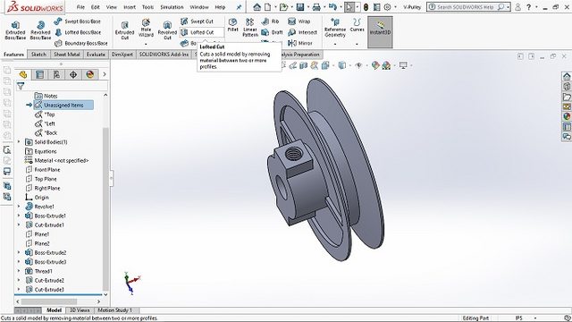
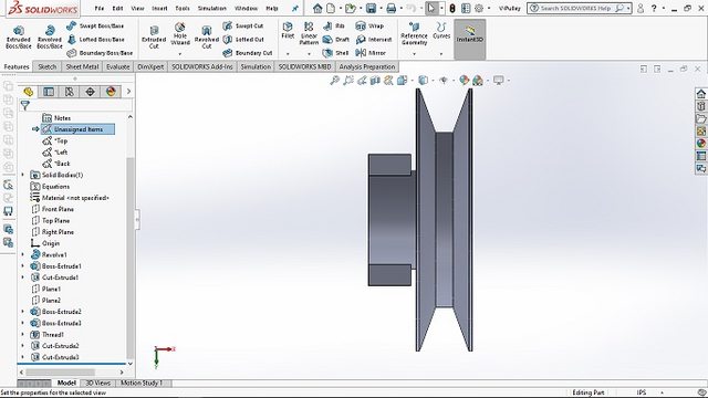
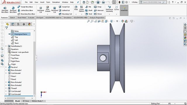
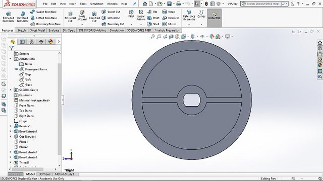
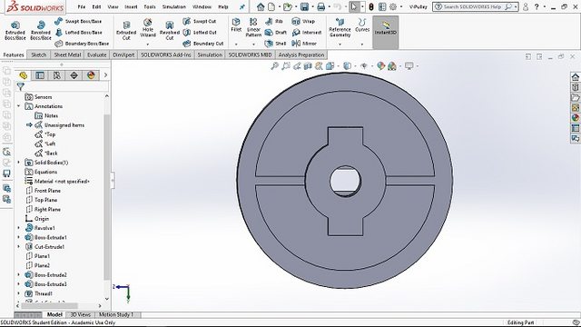
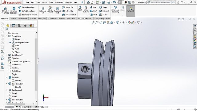
Here is what I am looking at. Most of these dimensions can be modified to make life easier on your side if needed.
The only two things I can change are the inside shaft diameter (has to fit the shaft of the motor I have) and the shaft length can be not shorter than specified (again to maintain clearance give the motor in hand).
Looking forward to your thoughts.