Yes, I get the clicking noise, lights work and the 24v ports and their lights work (indicator lights turn on/off when I turn on those ports) as they power my fans.
Having a clear pic would help, thank you so much!
Mine went down from simply unplugging it from the wall, then plugging it back in. Thanks for posting this!
Same issue here, commands ok and indicators lights (on and off), but partial outlets without energy.
Solved: After delete EB832 from my dashboard in https://apexfusion.com/ , and reconfiguring, it works fine until now... but I will not trust any more on my energy bar, afraid to travel now...
I'm curious, I have done the current sensing resistors in the past, on an eb832. I thought the same thing happened this time but the resister all tested good, no burn marks or hot spots on the board, but outlets 3 and 8 are not working correctly. if I unplug the eb832 and plug it back in it works until I toggle power on and off on the outlet in fusion, the LEDs are on and I hear an audible click when I toggle the switch in the off position, but not toggled in the on position. I have the same issue with both outlets. I have checked the resistors and they are good. any ideas?
Just an update. I found that if I have all outlets in the on position, turn outlet 8 off then on, it doesn't come back on. but if I toggle any 2 outlets to the off position outlet 8 will come on by its self in the toggled on position. In fact i just tested it with all the outlets and its the same for all of them. If i have let say an LED light plugged into any outlet and toggle all outlets in the on position the light works. If i turn that outlet with the light off then the outlet does not come back on until I toggle 2 separate outlets to the off position.
If i were to leave 2 outlets in the off position, all other outlets turn on and off as they should. If i switch them all back on, the 2 that were off do not come back on after toggled.
Just spitballing here as I have yet to tear into my bad eb832 yet, but it sounds like whatever power supply they are using to draw in the coils of the relays does not have enough current to drive them all.
(Again I am assuming that they are using one power supply to drive all.)
CAUTION- I am not liable for any damages to your person or property. This is offered as a possible solution to an electrical problem, and with this territory comes risk to your health and property that may not be directly mentioned. You should only attempt this repair if you are sure of your own safety when working with and around both soldering equipment and electronics.
If your eb832 has the following symptoms then you can probably repair. Be careful and ensure that your symptoms ALL align with the following, or it may be a different issue.
You can see the EB832 outlets in Fusion
Outlets do not power on or "click" when you switch them in Fusion
You can see the small indicator lights on the EB832 change as you change them in Fusion
You can hear a "click" when the 24v "Link" ports are switched on and off in Fusion
With these symptoms, we can say with a good amount of certainty that your 12v power supply has burned out. Don't worry, if you are out of warranty, it wont cost too much to fix.
You will need the following: (amazon links were not working)
soldering iron, solder, and a decent idea of how to use them safely
recommended but not required- 30mmx30mmx7mm 5v fan
search amazon "MakerFocus 2pcs Raspberry Pi DC Brushless Cooling Fan Heatsink Cooler Radiator Connector"
Jumping right in, unplug the EB832 with apex connected. Wait a few seconds, as this will make sure any remaining power in the eb832 is gone. You will need to remove the 3 screws on the back.
Once these are out, the shell is still held on the opposite side with little clips. Fold it open it like a book, being careful not to rip or stress the little white ribbon and the wires going to the cover. You will have this when you are open:
In the bottom right corner is the problem unit. seen closer here:
As you have probably recognized, it is pretty crazy that this entire product relies on a 2$ part to function at all. (edit- I removed a rant about Neptune)
Moving on, you will want to remove the fan connector. It is the small white connector next to the power supply. You just need to get it out of the way.
If you look at the small fan, you can carefully break the hot glue and pull it out. Set that aside and I will mention what to do with it in a few steps
At this point you can lift the main board and inspect the power supply. You will notice it floats above the main board, connected by 4 small pins. circled below are those pins. Your replacement power supply will not come with these pins, so we will take those off from the old supply.
I assume that if you are following this, that you are confident in you abilities to solder and de-solder a bit. If you have always wanted to learn how, this probably isn't a great project to just jump into, but it definitely could be done with very little knowledge. I will write the following will steps to follow but as far as the basics of soldering, you will need to find help elsewhere. Youtube has a lot of great videos, but to be honest I don't know what to recommend.
Removing the old board:
I would recommend heating up the solder from the bottom of the main board and rocking the power supply back and forth as you pull it. the 4 pins to heat and push through are circled here:
If you do this carefully the power supply will easily come free with the pins, leaving the holes in the main board. You should remove the pins and solder them to the new power supply in the same 4 holes. Once the power supply has pins, it is just a matter of soldering that back to the main board. It should be obvious from the distance between the pairs of pins, but the letters/numbers on the yellow component should face away from the edge of the main board. If you are bending pins to get them to line up, you may not be putting it in the correct direction :) Sorry if this isn't enough of an explanation for someone new to soldering, feel free to ask questions and either myself or one of the other members may be able to help.
At this point you could close it all up and everything should work fine. If you want to test before you close it up, you should see this red LED on the power supply.
Please take caution that there are plenty of live connections that would love to give you a jolt. So do this very carefully and don't touch anything in the power bar while it is connected to the wall, or for a time after disconnecting.
All that remains is that we need to have a look at the fan and do some coating to help reduce the likelihood of damages in the future.
Go ahead and peel the sicker off the back of the fan. This will expose the board that controls the fan. If enough salt or moisture had built up to connect these pins, then it is likely that this fan caused the power supply to fail. That slight mist of salt that builds up on all of your aquarium equipment, gets pulled in by this fan. It wouldn't need to get directly exposed to water to cause the failure of your whole EB832. (edit- removed more Neptune rant) Whatever, here is what I did with mine.
I didn't outright replace my fan, but I think that might be a better move. I linked a compatible version above. I just cleaned the salt and dust that had built up on my fan, and then painted conformal coating on its board. It wont stop everything, but it should help reduce the effects of salt. I then did that to the entire back of the EB832 main board, and around all of the pins on the top side.
Thank you for the very detailed repair instructions. I have 2 EB832's, and 1 stopped working caused by a blown utility pole transformer outside my house. Upon close inspection, I noticed one of the round transistors' top is bulging up on the 12V power supply.
Just repaired my EB832 with the part bought from Amazon. It took 18 days to arrive. Your instructions were simple and straight to the point. I wonder if this is a very common problem with the EB832.
Going off topic a bit, anyone here can point me to a thread in where to get the "steppermotor" for the DOS? The left motor of mine stopped working. I can't find this info anywhere here on R2R.
@2mk can you post a link for others to the amazon source? Would be a lot faster than me at shipping I think lol. As for the stepper motor, it probably isn't the motor unless the bearings gave out. If you open up the case it will have a sticker on the side that will have all of the requirements, and you should be able to find an exact replacement. If I had to guess it is a nema 17, but you will have to confirm with the name plate sticker or by measuring the "face" (with the shaft coming out) to see if it matches this:
nema stepper motors have standardized mounting faces, but the length "L" in the drawing changes depending on the amount of torque required.
I toyed around with replacing the dos stepper drivers with something more modern, as 3d printers have improved there has been a lot of development into silent stepper motors/drivers. the Neptune pcb does not lend itself well to this kind of modification, but if you were experienced enough, it surely could be done. @_AV if you can figure it out, I think a lot of people would love to pay for a service to have these stepper drivers hacked into their DOS..... I'd definitely be interested lol
I toyed around with replacing the dos stepper drivers with something more modern, as 3d printers have improved there has been a lot of development into silent stepper motors/drivers. the Neptune pcb does not lend itself well to this kind of modification, but if you were experienced enough, it surely could be done. @_AV if you can figure it out, I think a lot of people would love to pay for a service to have these stepper drivers hacked into their DOS..... I'd definitely be interested lol
@_AV I don't have a pic, but it is surface mount I'm fairly certain. just looked it up and I think the 2 ICs on either side of the larger chip may be the drivers. I can open mine up sometime if you are legitimately interested in adding a new service :)
@2mk I cant really make out the stepper models, but opening it would definitely find that info. They are definitely not exotic steppers
Just spitballing here as I have yet to tear into my bad eb832 yet, but it sounds like whatever power supply they are using to draw in the coils of the relays does not have enough current to drive them all.
(Again I am assuming that they are using one power supply to drive all.)
I think they are fine when the bar is running normally. It struggles to supply the huge influx of current when the power bar is turned back on and all the coils are asking for max current, all at once. As _AV noted in his capacitor rebuild post, the capacitors have a service life, and the capacitors on these PSU's have a very low life lol. They may work for a few years, but eventually plugging in your eb832 will draw too many amps for that poor PSU to supply and a cap gets bulged.
Anyone worried about their eb832 to check out @_AV 's thread below. It focuses more on fixing the core issue with this PSU, rather than just replacing the whole unit.
Some of my previous repairs: https://www.reef2reef.com/threads/radion-xr30-complete-no-light-repair.792711/ https://www.reef2reef.com/threads/radion-lights-board-level-repair.774331/ https://www.reef2reef.com/threads/ai-hydra-fan-connector-repair-significant-corrosion.793402/ First off, let me...
Agreed which is why I think so many of these die after a power outage. So I'm wondering if there is a way to program a delay for each outlet to stagger them turning back on when the EB832 is turned back on.
I think they are fine when the bar is running normally. It struggles to supply the huge influx of current when the power bar is turned back on and all the coils are asking for max current, all at once. As _AV noted in his capacitor rebuild post, the capacitors have a service life, and the capacitors on these PSU's have a very low life lol. They may work for a few years, but eventually plugging in your eb832 will draw too many amps for that poor PSU to supply and a cap gets bulged.
Anyone worried about their eb832 to check out @_AV 's thread below. It focuses more on fixing the core issue with this PSU, rather than just replacing the whole unit.
Some of my previous repairs: https://www.reef2reef.com/threads/radion-xr30-complete-no-light-repair.792711/ https://www.reef2reef.com/threads/radion-lights-board-level-repair.774331/ https://www.reef2reef.com/threads/ai-hydra-fan-connector-repair-significant-corrosion.793402/ First off, let me...
I kinda feel like we need to hold Neptune Systems' feet to the flame at this point. These can fail during a simple power outage and you're (we) totally screwed. All I did was unplug the unit, reroute some cables and plugged it back in, then poof. I have EB8's that are twice the age of my EB832 and they're still going strong without issue.
I need to step away, it still makes me so angry when I think about it.
This is amazing. I had a EB832 blow out after a power outage. I bought a new one and kept the old one for parts. It looks like for $10 i have a good working eb832! Now I just have to wait on shipping.
I kinda feel like we need to hold Neptune Systems' feet to the flame at this point. These can fail during a simple power outage and you're (we) totally screwed. All I did was unplug the unit, reroute some cables and plugged it back in, then poof. I have EB8's that are twice the age of my EB832 and they're still going strong without issue.
I need to step away, it still makes me so angry when I think about it.
@MadeForThat
Thanks again for everything!
My eb832 failed after a power outage. I replaced the part you suggested and it worked perfectly!!! Glad I kept the old one to repair!
@2mk can you post a link for others to the amazon source? Would be a lot faster than me at shipping I think lol. As for the stepper motor, it probably isn't the motor unless the bearings gave out. If you open up the case it will have a sticker on the side that will have all of the requirements, and you should be able to find an exact replacement. If I had to guess it is a nema 17, but you will have to confirm with the name plate sticker or by measuring the "face" (with the shaft coming out) to see if it matches this:
nema stepper motors have standardized mounting faces, but the length "L" in the drawing changes depending on the amount of torque required.
I toyed around with replacing the dos stepper drivers with something more modern, as 3d printers have improved there has been a lot of development into silent stepper motors/drivers. the Neptune pcb does not lend itself well to this kind of modification, but if you were experienced enough, it surely could be done. @_AV if you can figure it out, I think a lot of people would love to pay for a service to have these stepper drivers hacked into their DOS..... I'd definitely be interested lol
@MadeForThat The 12V part was bought from Amazon from the link you provided (Gazechimp) in your thread. just a few days ago I noticed there are two more sellers that sells the same thing in the USA instead of coming to china.
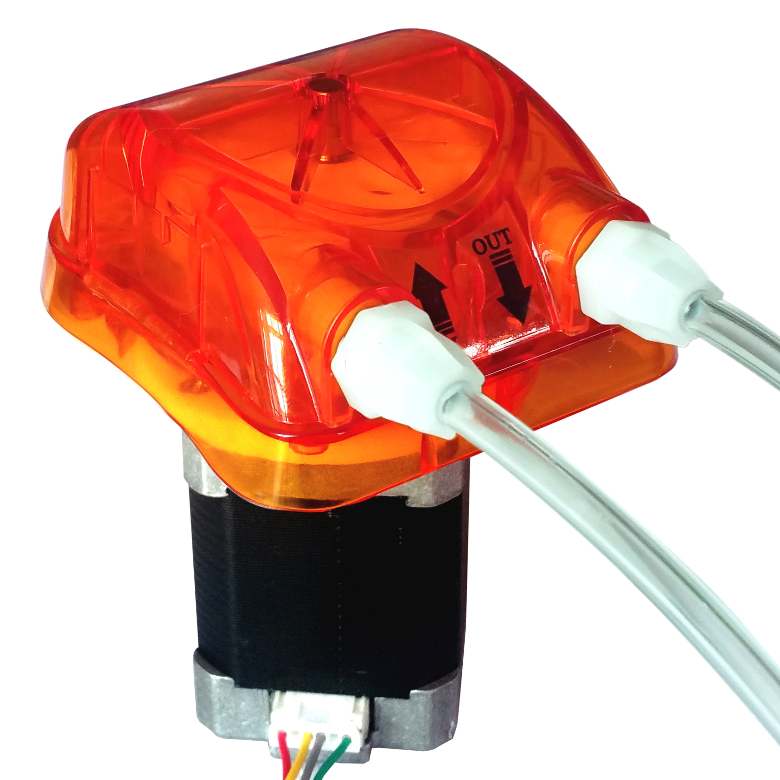
The picture I took after opening the DOS is above. The motor details are shown on stepper motor the label. I found a stepper motor on AliExpress for $65.00 that appears to be the same motor with the same specs but does not show the entire model number. Noted that it is from the same motor manufacturer. "
250ml/min, 4 Rollers, 24V Honlite Stepping Peristaltic Pump with Exchangeable Pump Head and PharMed BPT Peristaltic Tube"
I wonder if the above can be used as a replacement. Can you take a look at it and give me an opinion?
I am almost sure the problem with mine is a motor lock-up problem. I took the motor out and tried to disassemble it by removing the 4 screws show on the back of the motor to no avail. Nothing came apart. Then I force it to turn and it turned with a lot of effort. After re-installing it back in, It worked for a few minutes and ceased to work while making the same grinding sound, while the right motor right motor works fine.
As for the upgrade you mentioned and shown in pciture, what exactly are you are proposing? I am not well versed with electronics at all. Where is the part coming from and what part is being replaced in the DOS? Can you Clarify?