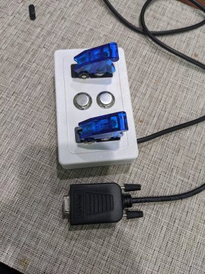
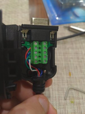
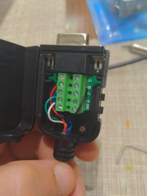
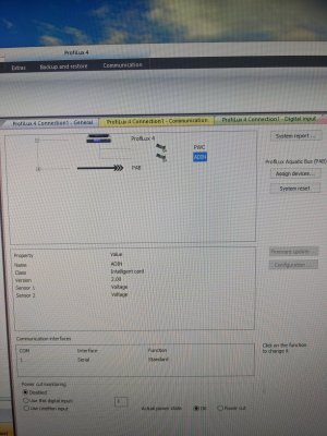
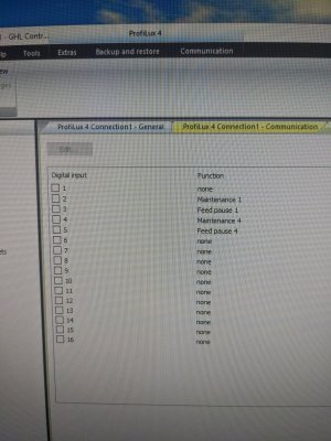
I installed adin card. Wired switches. Plugged the P4 back in. It shows adin in system settings. I see two new voltage meters on my app??? But when I go to digital input and set my 4 buttons up. I click on the digital input 1-4 and it just unchecks quickly in gcc. I try to check all the digital inputs to the same ending. It unchecks. Getting frustrated


Navigation
Install the app
How to install the app on iOS
Follow along with the video below to see how to install our site as a web app on your home screen.
Note: This feature may not be available in some browsers.
More options
You are using an out of date browser. It may not display this or other websites correctly.
You should upgrade or use an alternative browser.
You should upgrade or use an alternative browser.
Pl-adin switch box not working
- Thread starter Michael Gray
- Start date
- Tagged users None
Users Who Are Viewing This Thread (Total: 1, Members: 0, Guests: 1)
- Joined
- May 31, 2017
- Messages
- 1,930
- Reaction score
- 2,140

Digital Input - PL-ADIN card Usage Example
Let's talk about Analog & Digital Inputs. What are they, and what can you do with them? First things first - the name of the card. Analog Digital INput This topic comes up from time to time, looking to implement an extra Float switch, a relay, a manual switch or button to trigger actions etc...
 www.reef2reef.com
Are these two Wire Switches?
Then you would use Ground #8 and then for #1 for the first Switch then Ground #8 and then #2 for the second switch have yo tried that?
Then you would use Ground #8 and then for #1 for the first Switch then Ground #8 and then #2 for the second switch have yo tried that?
- Joined
- Oct 3, 2015
- Messages
- 5,145
- Reaction score
- 8,758
Are these two Wire Switches?
Then you would use Ground #8 and then for #1 for the first Switch then Ground #8 and then #2 for the second switch have yo tried that?
Yes, 1 common ground (black wire) for all switches and then individual wires for the other side of each switch.
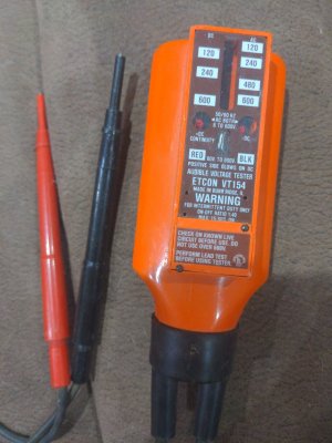
Then first he needs to use a continuity tester. He has the Green going to ground, and from the looks of it, the Black going to terminal 4.Yes, 1 common ground (black wire) for all switches and then individual wires for the other side of each switch.
And further more, the common ground should go to terminal 8 NOT the one labeled Ground.
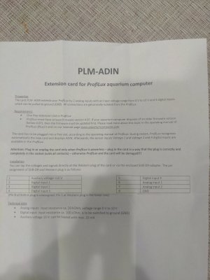
Also he has it wired on pin 1-4, it needs to be 2-5.
Using pin 1 (10v) could be why he's seeing voltage.
His connector has 10 terminals.

Also he has it wired on pin 1-4, it needs to be 2-5.
Using pin 1 (10v) could be why he's seeing voltage.
His connector has 10 terminals.
I have changed it to black ground. Put on ground. And 2-5 are switches. That part is done. Still nothing.
Are you saying black needs to go to 8. And not ground?
Are you saying black needs to go to 8. And not ground?
And I'll try that now. But I still can't check digital input boxes. Let me do it now
Did you get any paperwork or wire diagram with it you can share?
According to the other thread, you use terminals 2-5 and 8 is the ground.
Do you have a continuity tester?
According to the other thread, you use terminals 2-5 and 8 is the ground.
Do you have a continuity tester?
I just changed it and these are my settings but can't click on any of the dang digital input squares. Flipping all switches. Nothing is happening
Mike, I mean with the Break Out Box?
Not using the breakoutbox? I'm using the adin and connecting it to a db9 connector to switches.Mike, I mean with the Break Out Box?
By Break Out Box I am referring to the switch box you are using. Did he tell what wire was the ground/common?Not using the breakoutbox? I'm using the adin and connecting it to a db9 connector to switches.
Ya

Similar threads
- Replies
- 2
- Views
- 215
- Replies
- 3
- Views
- 219
New Posts
-
-
-
*** TUNZE PREMIUM GLASS CARE GIVEAWAY!!! *** Two Prizes for Two Winners!!!
- Latest: Reefing_addiction
-

