Navigation
Install the app
How to install the app on iOS
Follow along with the video below to see how to install our site as a web app on your home screen.
Note: This feature may not be available in some browsers.
More options
You are using an out of date browser. It may not display this or other websites correctly.
You should upgrade or use an alternative browser.
You should upgrade or use an alternative browser.
Fixing an EB832 with non-functional outlets but does have functional indicator lights
- Thread starter MadeForThat
- Start date
- Tagged users None
They're not that expensive and with a little practice, you can learn how to, especially with YouTube as your source. Cooper-Weller's are great for fixed temp irons (and variable temp, but are a little expensive), but you can pick up a variable temp iron for cheap and they're pretty good. I bought this one a few years ago and it has served me well. Hakko Digital Ironthis thread is awesome. i wish i had a soldering iron and knew how to use it
Also if you search amazon for "soldering learning kit" you will get all kinds of fun projects that you can practice on and at the worst be out a few dollars. When I first started I ruined 2 of those kits, but learned from it. After fixing two of these bars I have covered the cost of that practice many times over haha!
- Joined
- Nov 11, 2018
- Messages
- 462
- Reaction score
- 157
replacement bar comes in a few days, after which i will have this. i am interested in learning for sure but im not sute this is the project to learn with.
did watch some YouTube vids. already learned quite a bit. e.g. i was doing the newbie thing and always tried to drip the solder onto the connection. never realized the copper ring around the hole is where you apply the tip. and that mesh braided copper for desolder cool stuff
did watch some YouTube vids. already learned quite a bit. e.g. i was doing the newbie thing and always tried to drip the solder onto the connection. never realized the copper ring around the hole is where you apply the tip. and that mesh braided copper for desolder cool stuff
Yeah in my opinion after seeing it done, and seeing what a good connection looks like, anyone can solder a starter kit. It can sometimes be tricky and takes a few tries to get the solder to flow just right. Don't be afraid to let everything cool down and try again!
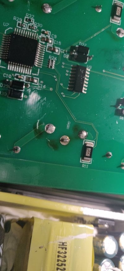
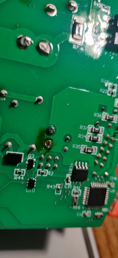
@minus9 here is the pics of the main board, there are some dark spots that are from when they originally assembled the board, is it possible that the darkness on yours is also from this?


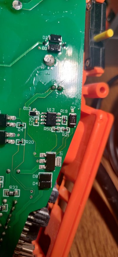
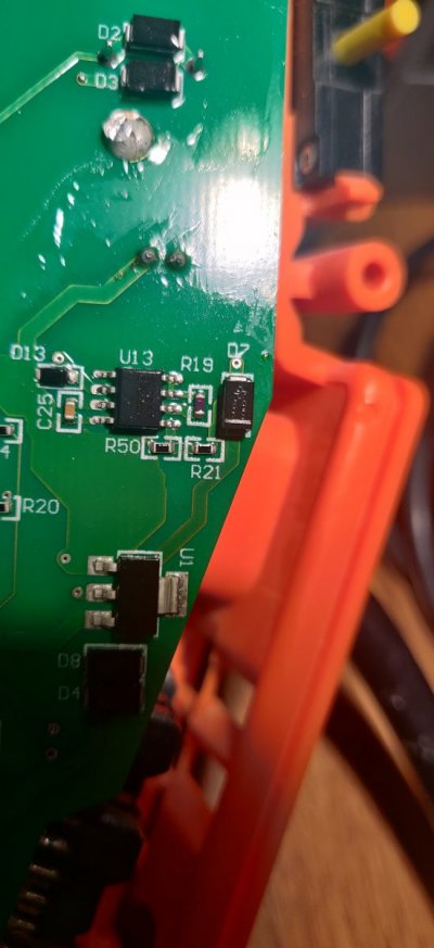
I wish it was just from assembly, but the resistors R19, 21 & 50 are all fried on my board. I'll probably own mine up this weekend and see if the 12v supply is torched or not? It only seems to be the ac outlets on mine that are the issue. Can you get a number on the resistors I listed from your unit? I'll try to zoom in, but you can probably get a better close up or simply use a magnifying glass?@minus9 here is the pics of the main board, there are some dark spots that are from when they originally assembled the board, is it possible that the darkness on yours is also from this?


You can clearly see the burn radius on the resistors.
Well, I was able to order the parts off of Amazon, and everything arrived earlier today. I replaced the buck converter and the fan and it's now working like new. Thank you very much for the thread.
Nice!Well, I was able to order the parts off of Amazon, and everything arrived earlier today. I replaced the buck converter and the fan and it's now working like new. Thank you very much for the thread.
Just replaced the ac-dv converter in my eb832, followed this thread and it is back up and running now!! $7 part saved me a couple hundred!! Thanks for explaining what went bad and how to fix it!!
@Mallard @scooter24 glad to hear you two are sorted out! Please try to point others to help if you see that this may help them!
- Joined
- Nov 11, 2018
- Messages
- 462
- Reaction score
- 157
Installed my replacement eb-832 tonight. I ordered the part off of Amazon I know like $8 more but I just assume have it sooner rather than later. Turns out that I have a buddy who works on pcbs for a living so I plan to video the repair process I'll have him talk his way through it as he's doing it hopefully we'll be able to put up on YouTube and share here for other. Big Cheers to @MadeForThat for starting this thread it has been very very helpful
@becon776 I'm glad to hear, a video would be great! So far just from the responses I have gotten, this has saved the community a few thousand dollars in just a few weeks. That is money they can use to build better reefs and buy new fancy equipment, rather than replace something they already bought. For all the help that the community has given me over the years, it was really the least I could do. Hopefully this thread will help people for years to come in one way or another. cheers!
1-4-2021
1-4-2021
- Joined
- Oct 3, 2019
- Messages
- 679
- Reaction score
- 694
Have you tested those resistors yet? Resistors don't fail often, but when they do, they usually fail open, meaning they do not conduct at all.
You can clearly see the burn radius on the resistors.
It's hard to tell from the picture, but it looks like the two bottom resistors have had some work done on them. Both have too much solder on one side and there is some mess on the trace off of the diode.
If, in fact, it's not related to a prior repair, but actually caused by a component failure, your problem is likely not the resistors, but whatever caused the short, potentially the inverter they are attached to.
But to answer your question, just look up the datasheet schematics for the inverter. It appears to be a standard step down converter configuration. R19 = Rsc 0.33, R21 = 3.6K, R50 = 1.2K
Last edited:
I haven't pulled them from the board yet, but they're fried. It's not from a bad solder job, if it was, then they have really bad QC. I'm going to test each component they are connected to, so we'll see if the damage goes further? Too many other things on my plate right now, so this will have to wait.Have you tested those resistor yet? Resistors don't fail often, but when they do, they usually fail open, meaning they do not conduct at all.
It's hard to tell from the picture, but it looks like the two bottom resistors have had some work done on them. Both have too much solder on one side and there is some mess on the trace off of the diode.
If, in fact, it's not related to a prior repair, but actually caused by a component failure, your problem is likely not the resistors, but whatever caused the short, potentially the inverter they are attached to.
- Joined
- Oct 3, 2019
- Messages
- 679
- Reaction score
- 694
I have seen worse coming from Neptune.I haven't pulled them from the board yet, but they're fried. It's not from a bad solder job, if it was, then they have really bad QC. I'm going to test each component they are connected to, so we'll see if the damage goes further? Too many other things on my plate right now, so this will have to wait.
I'd first test the resistors in circuit. if they are fried, open line will be detected. But even if they are fried, they are the casualty of something else failing.
@_AV what utilities do you recon this chip is supplying? Referring to that diagram- I wonder if 24vdc was able to jump from pin 5 to 6 with some salt, and from there roast the "r1 and r2". Speculation of course. I am also curious, if the "Rsc" was changed, would this modify the output voltage? I have some electronics experience, but am by no means an electrical engineer, so most of the TI datasheet is too deep down that rabbit hole for me to reasonably investigate.
- Joined
- Oct 3, 2019
- Messages
- 679
- Reaction score
- 694
It's probably providing 5V to the EB832 onboard controller (U7). It's probably not the salt per se, but more likely an internal short on the IC.
Rsc is a shunt resistor used for current sensing. It has almost no resistance as you can see. It is there mostly for current limiting purposes. Changing the resistor would change the maximum current that goes through the buck converter in case of a short. So technically it's designed to protect the converter against a short in the circuit. Unless of course the converter itself becomes a short.
Rsc is a shunt resistor used for current sensing. It has almost no resistance as you can see. It is there mostly for current limiting purposes. Changing the resistor would change the maximum current that goes through the buck converter in case of a short. So technically it's designed to protect the converter against a short in the circuit. Unless of course the converter itself becomes a short.
Similar threads
- Replies
- 1
- Views
- 174
- Replies
- 16
- Views
- 456
- Replies
- 22
- Views
- 548
- Replies
- 2
- Views
- 163
New Posts
-
-
-
-
ARC Auctions | $29 Shipping | No Reserves - Ending Sat 4/20 9pm ET
- Latest: A Reef Creation


