reef-pi :: An opensource reef tank controller based on Raspberry Pi.

larrybari

New Member
View Badges
Joined
Oct 30, 2021
Messages
8
Reaction score
3
Location
Launceston, Tasmania
Rating - 0%
0   0   0
Hi, I've got an issue with My ATO pump that I've now got working properly, but can't seem to reset so the charts look normal... I get this error
1668040281767.png
 

tyronbes

New Member
View Badges
Joined
Nov 5, 2022
Messages
20
Reaction score
57
Location
Austin
Rating - 0%
0   0   0
Welcome to the development thread of reef-pi, an open-source, affordable, modular DIY reef-tank controller based on Raspberry Pi.

aio.jpg

If you are trying to build a reef-pi controller, please check out the build guides linked below. You can use this thread to seek help and to stay updated with the latest development.

Screen Shot 2018-11-04 at 8.38.50 PM.png


reef-pi provides following functionalities:
  • Equipment control or automated power strip (including digital timers to switch on/off equipment at periodic intervals)
  • LED light control (24 hour cycle), diurnal cycle, fixed dimmig
  • Auto Top Off (based on photoelectric water level sensor or float switch)
  • Temperature monitoring and control (switch on/off heater & chiller)
  • pH monitoring
  • Dosing automation
  • Macro (feed mode etc)
  • And several other features like camera controls (periodic image capture and upload on google drive), telemetry (dashboard and alerting based on sensor values using adafruit.io), mobile friendly UI etc.
A beginner friendly list of reef-pi build guides are available on adafruit.io, if you are planning to build a reef-pi controller start with them.
  1. Setup and installation
  2. Power controller
  3. Temperature controller
  4. Auto Top Off
  5. Light controller
  6. pH monitor
Since reef-pi is modular and customizable, the cost of individual builds varies. In our experience reef-pi controller are almost always cheaper than the commercial alternatives and costs anywhere between 100 to 550 USD. An example bill of materials can be found here as amazon list. If you are building a reef-pi controller, I highly encorage you start a build thread and tag it with #reefpi to seek help with your build


--------------------------- Original thread start ---------------------
Hello friends,
I am starting a master thread for a DIY reef tank controller that is based on all opensource software and hardware. I had started with this project with following goals:
- Build an opensource software and hardware based reeftank controller that anyone can use and hack
- Keep the controller well tested against a set of standard equipment I use, while make it possible for other equipment to be used
- Maintain my own tank build threads and their evolution, backed by this controller.
- Learn electronics and reef keeping along the way (I am biologist by education & software engineer by occupation)

Following are the details of what I have developed & tested till now:
Controller software:
- The main controller software is called reef-pi. It is written in go, its fast and performant. It used embd for hardware communication. It also runs a little web server which provides the UI for the controller. UI is written in React , and can be accessed from anything that has web browser. As of now, the reef-pi supports following things:
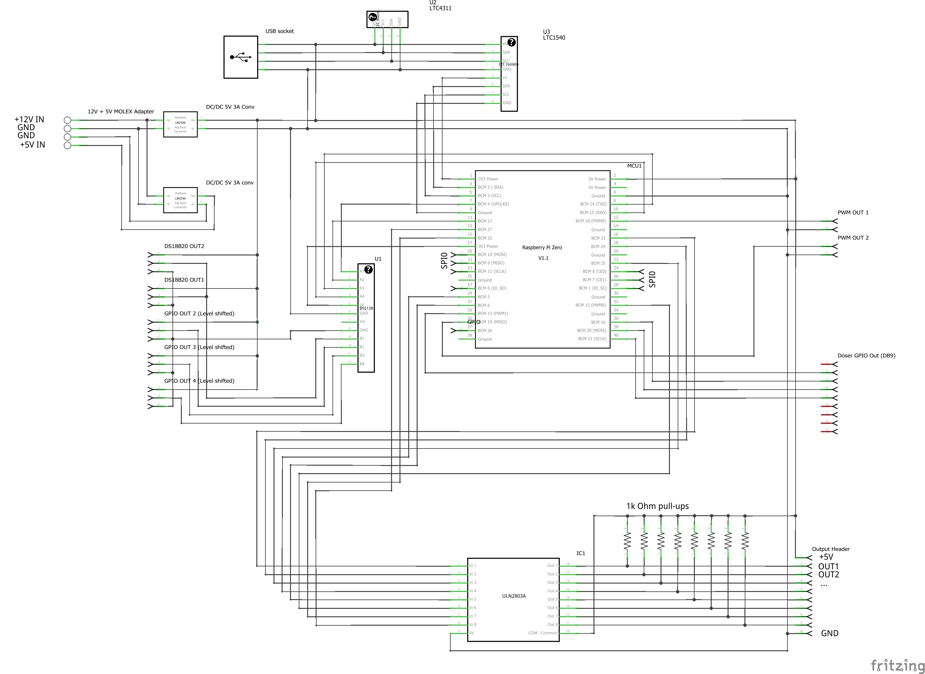
- AC 110/220 V socket on/off (uses optocoupled relays underneath). This is used to remotely switch on/off return pump, LED bulb, heater etc.
- 0-20 Volt DC PWM. This is used to control things like dimmable LEDs, DC pumps. I use it to control my Kessil A80, A360. As well as a 5V DC pump (i use it as wave maker in one of my pico with SPS). PWM is done using PCA9685 breakout board from adafruit. This board supports 16 channels. I am using only 5 at max, as of now.
- Analog sensor support using MCP3008 analog to digital converter. This supports 8 channels. i.e. I can use up to 8 sensors/probes. As of now, I have only tested temperature sensor with it.
Other than the following basic hardware/equipment support, the controller software provides following additional features:
- Setting up daily/weekly/monthly scheduled jobs. Like turning on/off certain equipment. I use this feature to run my AC20 HOB filter nightly.
- Setting up dusk-to-dawn like lighting using PWM. The UI gives 12 vertical slider based 0-24 hours (each slider representing 2 hours gaps). I combine two of these two control the kessil LEDs.
- Authentication using Google OAuth. Since the whole controller runs on raspberry pi and provides an web frontend, security of one of my concern. To mitigate this, I have added google authentication support, which when configured will allow only certain users to log in (email specified in the configuration value).

This is the summary of the core controller software and what features it has as of now. I am constantly writing/improving things around it. As of now, I have two reef tank powered by this. I 'll have seperate threads on the individual builds that will include the housing and ancillary hardware in nano-reef.com, as my tank build threads are there, but I'll share all the controller specific common bits here, including UI screen shots, and tank pics :)

20161115_081550.jpg
So much awesomeness here!! I started building my reef pi about a week or so go, I'm following a tutorial on learn adafruit, decided to go with making my own 8 channel relay outlets, I'm not exactly sure what is going on, I can get in2 to come on and off, in4-8 stay on, and 1&3 do nothing. Did you have to do any coding on python to get your relay to work? I've noticed theres 2 different gpio pinot diagrams, not sure which one to follow. But I'm slowely getting it going, in the tutorial they are using a premade relay outlet, so it's definitely been an interesting trial and error so far. But I'm glad I stumbled upon your post, I'm going to read through it and see what valuable info I can get!
 

geekengineer

Active Member
View Badges
Joined
Feb 10, 2019
Messages
427
Reaction score
538
Location
South Aurora
Rating - 0%
0   0   0
Hi, I've got an issue with My ATO pump that I've now got working properly, but can't seem to reset so the charts look normal... I get this error
1668040281767.png
Sorry to Jest but this error message sort of makes it sound like your ATO bucket is empty. lol Anyways hopefully figure it out.
 

geologeek

Community Member
View Badges
Joined
Apr 21, 2010
Messages
65
Reaction score
39
Location
UK
Rating - 0%
0   0   0
Hi all, i am just looking for some advice.....

My reef-pi setup has been working wonderfully for the last 2 years without any hiccups whatsoever but unfortunately this changed on friday night when i could not access the UI via my phone or browser and Putty would not allow me to access the Pi via ssh despite the right password etc being used :confused-face:

So my only remedy i could think of was to pull my sd card and put it into another raspberry pi and temporarily adding init=/bin/sh to the end of /boot/cmdline.txt and resetting the pi password.

i was then thankfully able to ssh back into the Pi and disable/re-enable the reef pi service and POW i was back up and running with access via the UI :beaming-face-with-smiling-eyes::cool:

Now unfortunately i am left with a couple of problems.........7 of my 8 relays on the power module have failed and one of my temp sensors has gone haywire - it was the one controlling my heater so i have had to plug the heater into this last functioning relay and use my secondary temp probe to control it. All my equipment still works as they were initially wired up NC so they have power still, just now cannot be controlled. Will have to do a rebuild and sort that issue out as i dont think the last relay has much life left as it is clicking like crazy when the heater needs to be on.


So there is my story - now for the request for some assistance if i can?

on one of my channels in the Equipment section of the UI (Channel 2) even though it has no function now given the relay has failed it gives me the following error if i turn the channel on/off

{"error":"Failed to update. Error: can't set output on channel 8: open /sys/class/gpio/gpio8/direction: no such file or directory"} | HTTP 500

Anyone care to enlighten me as to why this is the case? Is it something as simple as the wire has come loose somehow or is this software side?

I will be completely starting a fresh with this build - i just need to figure out a new housing as i originally have it as an all in one enclosure - but have found that it would probably be best if i split it into at least 3 seperate modules for future maintenance and especially keep my AC side away from the controller side..........not sure if this is why the problem started in the first instance with some sort of power surge or something? cant see it has given the tank is meant to have a surge protector at the outlet..........

Anyway some guidance on the above error would be apprecited thanks!

Hope you are all good and happily reefing!
 

Sral

Valuable Member
View Badges
Joined
May 2, 2022
Messages
1,005
Reaction score
971
Location
Germany
Rating - 0%
0   0   0
So much awesomeness here!! I started building my reef pi about a week or so go, I'm following a tutorial on learn adafruit, decided to go with making my own 8 channel relay outlets, I'm not exactly sure what is going on, I can get in2 to come on and off, in4-8 stay on, and 1&3 do nothing. Did you have to do any coding on python to get your relay to work? I've noticed theres 2 different gpio pinot diagrams, not sure which one to follow. But I'm slowely getting it going, in the tutorial they are using a premade relay outlet, so it's definitely been an interesting trial and error so far. But I'm glad I stumbled upon your post, I'm going to read through it and see what valuable info I can get!
Welcome to the club !
I didn't have to do any coding for my Outlets. Personally I used an 8 channel Relay board from Robotank and connected that to my Raspberry Pi Zero on the GPIO Pins Number 7,8,9,10,11,23,24,25 using a ULN2803A transistor brick (Bottom part of the circuit drawing):
PiUnit_schem.png


OUT1 to OUT8 feed directly into the Relay board IN1 to IN8 as displyed here (not that visible, but the DB9 connector pins at the bottom feed directly into the IN1 to IN8 pins of the board, which are soldered directly to this mint board, just in front of the DIP18 socket and the lower row of screw terminals with the color coded wires from the DB9 connector):
4e99d86c-ade4-4b2c-aa98-693c1ed6cc4d-jpeg.2721327


I defined the PIns as outlet Connectors in the Configuration Tab:
1668341893636.png


I then defined some Equipment that uses those Outlets in the Equipment Tab:
1668342123157.png
 

Sral

Valuable Member
View Badges
Joined
May 2, 2022
Messages
1,005
Reaction score
971
Location
Germany
Rating - 0%
0   0   0
Hi all, i am just looking for some advice.....

My reef-pi setup has been working wonderfully for the last 2 years without any hiccups whatsoever but unfortunately this changed on friday night when i could not access the UI via my phone or browser and Putty would not allow me to access the Pi via ssh despite the right password etc being used :confused-face:

So my only remedy i could think of was to pull my sd card and put it into another raspberry pi and temporarily adding init=/bin/sh to the end of /boot/cmdline.txt and resetting the pi password.

i was then thankfully able to ssh back into the Pi and disable/re-enable the reef pi service and POW i was back up and running with access via the UI :beaming-face-with-smiling-eyes::cool:

Now unfortunately i am left with a couple of problems.........7 of my 8 relays on the power module have failed and one of my temp sensors has gone haywire - it was the one controlling my heater so i have had to plug the heater into this last functioning relay and use my secondary temp probe to control it. All my equipment still works as they were initially wired up NC so they have power still, just now cannot be controlled. Will have to do a rebuild and sort that issue out as i dont think the last relay has much life left as it is clicking like crazy when the heater needs to be on.


So there is my story - now for the request for some assistance if i can?

on one of my channels in the Equipment section of the UI (Channel 2) even though it has no function now given the relay has failed it gives me the following error if i turn the channel on/off


Anyone care to enlighten me as to why this is the case? Is it something as simple as the wire has come loose somehow or is this software side?

I will be completely starting a fresh with this build - i just need to figure out a new housing as i originally have it as an all in one enclosure - but have found that it would probably be best if i split it into at least 3 seperate modules for future maintenance and especially keep my AC side away from the controller side..........not sure if this is why the problem started in the first instance with some sort of power surge or something? cant see it has given the tank is meant to have a surge protector at the outlet..........

Anyway some guidance on the above error would be apprecited thanks!

Hope you are all good and happily reefing!
Unfortunate to hear.
That error points to a software or hardware error on the PI. Since that Outlet would only give OUT a signal, it doesn't care if something is connected or not. If I'm not mistaken, that error says, that the Reef-Pi software can't find the interface to set the GPIO Pin 8. That means it's software and should resolve once you reinstall Raspbian and Reef-PI.

I would recommend to save your Reef-PI's database using WinSCP for example. Settings are pretty much the same as for Putty.
 

geologeek

Community Member
View Badges
Joined
Apr 21, 2010
Messages
65
Reaction score
39
Location
UK
Rating - 0%
0   0   0
Thanks for the reply Sral

I would recommend to save your Reef-PI's database using WinSCP for example. Settings are pretty much the same as for Putty.


I have followed the advice - but there only appears to be old databases (reef-pi 3.5 and 4.0) in there and nothing with the newer more recent database for 5.3...........This is not really an issue as i need to do a full rebuild anyway, just something that caught my eye.

i do like the look of WinSCP - so thanks for that!
 

Sral

Valuable Member
View Badges
Joined
May 2, 2022
Messages
1,005
Reaction score
971
Location
Germany
Rating - 0%
0   0   0
Thanks for the reply Sral


I have followed the advice - but there only appears to be old databases (reef-pi 3.5 and 4.0) in there and nothing with the newer more recent database for 5.3...........This is not really an issue as i need to do a full rebuild anyway, just something that caught my eye.

i do like the look of WinSCP - so thanks for that!
You're very welcome !
I do however believe that those files have been old instal files. The Troubleshooting Guide mentions the DataBase location as:
Code:
Database storage file (default "/var/lib/reef-pi/reef-pi.db")

You can also download the file in newer Versions from the Reef-Pi Configuration Tab -> Admin, if I remember correctly.
 

tyronbes

New Member
View Badges
Joined
Nov 5, 2022
Messages
20
Reaction score
57
Location
Austin
Rating - 0%
0   0   0
Welcome to the club !
I didn't have to do any coding for my Outlets. Personally I used an 8 channel Relay board from Robotank and connected that to my Raspberry Pi Zero on the GPIO Pins Number 7,8,9,10,11,23,24,25 using a ULN2803A transistor brick (Bottom part of the circuit drawing):
PiUnit_schem.png


OUT1 to OUT8 feed directly into the Relay board IN1 to IN8 as displyed here (not that visible, but the DB9 connector pins at the bottom feed directly into the IN1 to IN8 pins of the board, which are soldered directly to this mint board, just in front of the DIP18 socket and the lower row of screw terminals with the color coded wires from the DB9 connector):
4e99d86c-ade4-4b2c-aa98-693c1ed6cc4d-jpeg.2721327


I defined the PIns as outlet Connectors in the Configuration Tab:
1668341893636.png


I then defined some Equipment that uses those Outlets in the Equipment Tab:
1668342123157.png
Hmm, the relay is the same one I found on amazon, granted I wish I remembered robo-tank haha prices are cheaper than the one I got on amazon! Anyway, interesting that your using the uln2803a, none of the tutorials I've seen mentioned anything about it. I'll pick one of those guys up and try it again, also!! Thabk you for providing the wiring diagram! That's by far the most detailed drawing ive seen so far. I'm sure it's going to help me out and a bunch of others tremendously!
 

Sral

Valuable Member
View Badges
Joined
May 2, 2022
Messages
1,005
Reaction score
971
Location
Germany
Rating - 0%
0   0   0
Hmm, the relay is the same one I found on amazon, granted I wish I remembered robo-tank haha prices are cheaper than the one I got on amazon! Anyway, interesting that your using the uln2803a, none of the tutorials I've seen mentioned anything about it. I'll pick one of those guys up and try it again, also!! Thabk you for providing the wiring diagram! That's by far the most detailed drawing ive seen so far. I'm sure it's going to help me out and a bunch of others tremendously!
You’re welcome ! Those relay boards can be a little tricky, you need to supply them their VCC (for me 5V), GND and the 8 signal pins. The relay actually activates when the Input Pin is connected to GND and can sink around 5mA.That’s why you should use a transistor, be it a n-MOSFET or npn transistor. You actually don’t even need the pull-up resistors I have used there, since the signal is a current, not a voltage.
 
Last edited:

zab34

Active Member
View Badges
Joined
Jan 23, 2012
Messages
335
Reaction score
71
Location
Orlando
Rating - 0%
0   0   0
On another note. I have fully 3d printed a rollermat that is now controlled by Pi.

right now I’d like setup it up a timer to activate the motor until I get the float switch fully dialed into position.
 

Attachments

  • 4E6148A2-4FA2-4D29-BAD0-5AFE3218C218.jpeg
    4E6148A2-4FA2-4D29-BAD0-5AFE3218C218.jpeg
    136 KB · Views: 48
  • D30250FB-48E2-4445-8E2E-51C164191F00.jpeg
    D30250FB-48E2-4445-8E2E-51C164191F00.jpeg
    179.3 KB · Views: 44

geologeek

Community Member
View Badges
Joined
Apr 21, 2010
Messages
65
Reaction score
39
Location
UK
Rating - 0%
0   0   0
Last edited:

bishoptf

Valuable Member
View Badges
Joined
Jan 1, 2019
Messages
1,344
Reaction score
1,720
Location
Missouri
Rating - 0%
0   0   0
On another note. I have fully 3d printed a rollermat that is now controlled by Pi.

right now I’d like setup it up a timer to activate the motor until I get the float switch fully dialed into position.
Id like to make one, have you posted the files on thingiverse or how can I get a hold of the files. Would also love to know about the dimensions, I have a small sump but would love to figure out how to incorporate it into my setup.

Thanks
 

bishoptf

Valuable Member
View Badges
Joined
Jan 1, 2019
Messages
1,344
Reaction score
1,720
Location
Missouri
Rating - 0%
0   0   0
On another note, I have a fully modified 165W viparspectra with moon lights that I am selling, have it listed on ebay right now but most are wanting me to put it back on stock timers which is lame, if anyone is interested in more information shoot me a PM. Basically set up to control the 2 main led channels then there is led strips that is also controlled via reef-pi. I went with a larger unit and this one has been sitting around and thought someone else should be getting some use out of it.
 

zab34

Active Member
View Badges
Joined
Jan 23, 2012
Messages
335
Reaction score
71
Location
Orlando
Rating - 0%
0   0   0
Id like to make one, have you posted the files on thingiverse or how can I get a hold of the files. Would also love to know about the dimensions, I have a small sump but would love to figure out how to incorporate it into my setup.

Thanks
I have not yet. It has only been on my tank for a few days. The print was also rather large about the size of shoebox once assembled. Most components were printed on my sidewinder x1, as the parts were too large for the prusa.
 

bishoptf

Valuable Member
View Badges
Joined
Jan 1, 2019
Messages
1,344
Reaction score
1,720
Location
Missouri
Rating - 0%
0   0   0
I have not yet. It has only been on my tank for a few days. The print was also rather large about the size of shoebox once assembled. Most components were printed on my sidewinder x1, as the parts were too large for the prusa.
Bummer I have a smaller 3d printer but I would still be interested in the files since I would like to try to scale things down for my nano tank, looks like something that would be neat to play with over the winter. Even if I can get the stl files I can chop and slice things up, once you have it fully operational would be nice to see all the details. I would probably just use it on a timer, would be a simple path and probably work most of the time.
 

A worm with high fashion and practical utility: Have you ever kept feather dusters in your reef aquarium?

  • I currently have feather dusters in my tank.

    Votes: 67 37.6%
  • Not currently, but I have had feather dusters in my tank in the past.

    Votes: 59 33.1%
  • I have not had feather dusters, but I hope to in the future.

    Votes: 25 14.0%
  • I have no plans to have feather dusters in my tank.

    Votes: 27 15.2%
  • Other.

    Votes: 0 0.0%
Back
Top