So, I read this entire thread, but I really only wanted the software DOS tracking that the DDR provides. I don't really care about the water level sensors, as I can just watch the dashboard items to monitor the actual levels. I have 4 DOS pumps for various things, and it's not practical to buy DDR for each one of them, just to get fluid monitoring. Although everything here is already mentioned at various points in this thread, I though I'd summarize how to make a DIY fluid monitoring connection for a DOS pump for those who don't want to read the entire thread.
1) I bought the following item from Amazon:
Amazon product ASIN B07QDXM34S . If this link gets outdated, you can search amazon for the following part number: 245132-0605
2) upon cutting the wire in half, I used a continuity tester to verify that the green wire correlated to pin position
#4, and the Orange wire correlated to PIN position 6 (as described earlier in this thread)
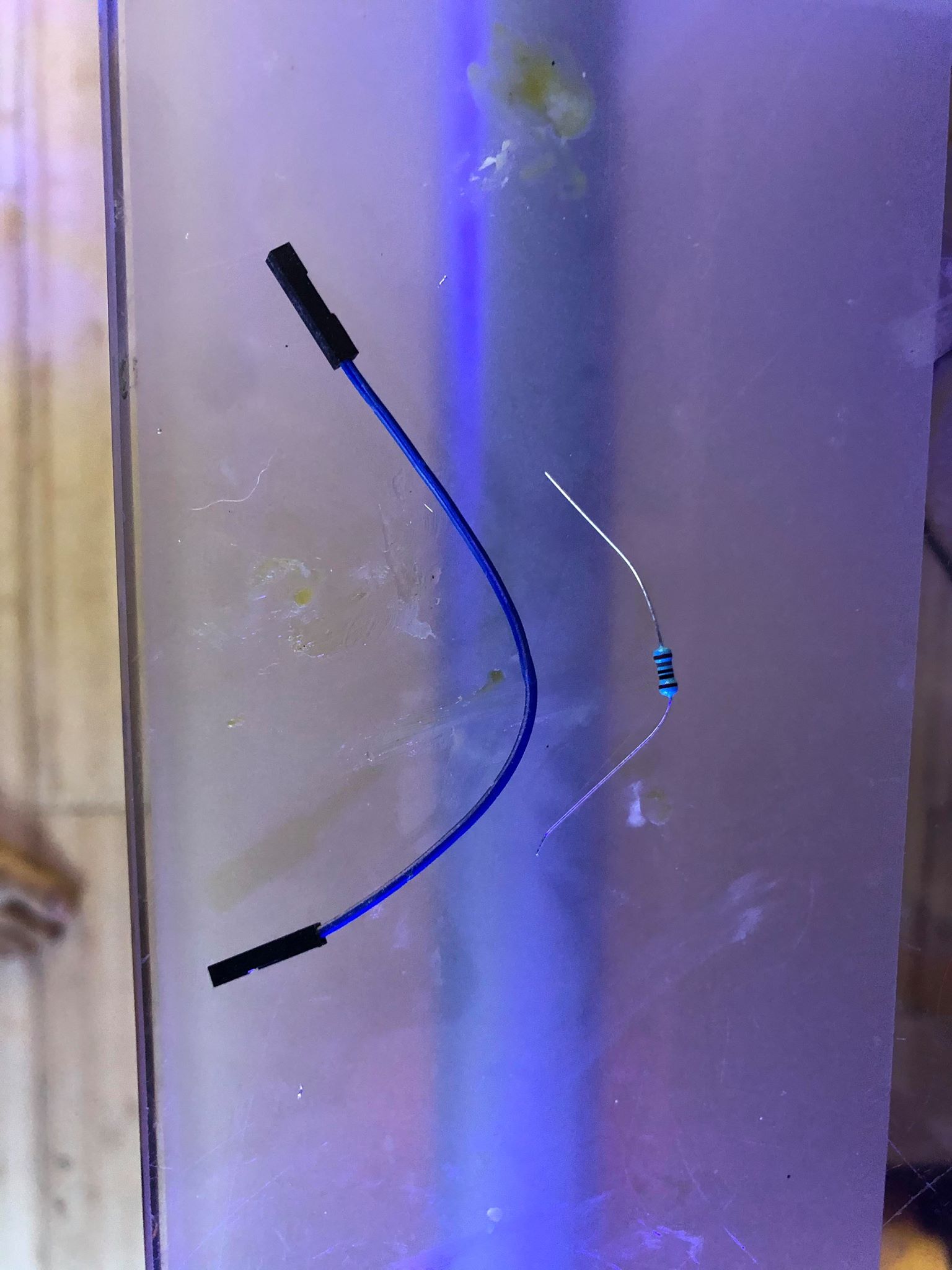
3) I soldered in a resister that is 150ohm, 1/4 watt, 5%. Here is the amazon link, but there are several various options:
Amazon product ASIN B00B5KZN92
4) I then used electrical tape to seal the entire thing up nicely:
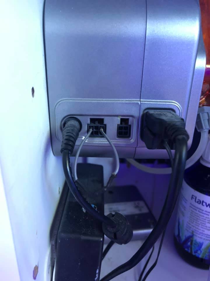
5) Then, you just plug the dongle in, and you get the Apex dashboard item for fluid monitoring, just as if you had a DDR connected.
Thanks to all the folks who figured this out earlier in this thread. The thread is really describing how to enable the optical sensors, but since all that I wanted was fluid monitoring, I thought I'd share how to do just that part cheaply and easily.....