https://www.amazon.com/gp/aw/d/B008UY5WL0 what i bought for the rj45 connections. I actually like the ease of wiring/cost. I hate audio jacks, i always mis wire them lol.
Follow along with the video below to see how to install our site as a web app on your home screen.
Note: This feature may not be available in some browsers.
https://www.amazon.com/gp/aw/d/B008UY5WL0 what i bought for the rj45 connections. I actually like the ease of wiring/cost. I hate audio jacks, i always mis wire them lol.
Hi all,
![]()
![]()
It is ready and working well.. I did not make pictures yet. But they will be placed later.
Keep in mind that if you are going to use my schema, IT IS HIGH VOLTAGE and DANGEROUS for humans.
Nice - like the inclusion of a fuse here :)
Do you have heatsinks on the BTA16 Triacs? Looks like max PD at 3A RMS is about 2-3W?
It is 3A fast fuse. Just to protect against shorting. So max 3A total (all 4). I will never drive than mutch. I used 16A triacs just because I still had them. Now, one is driving my 15W light. (15/240=62mA) Don't think you ever will notice any power dissipation in the triac. If you want to drive more power, you might want heatsinks. But TO220 can also dissipate without heatsink. I never did calculate it, but I have done a lot with triacs and from my experiance you need cooling on those if you drive more than about 3A for one triac that is switching 240V. You might always want to check after using a bit. (Kill the power first)
greetings.
Love it.While I want to dive into the software more, I've been spending some time conceptualizing a "base board" for a Raspberry Pi which has most of the common I/O circuits, power supplies, etc into a single board solution that will work with Reef-Pi.
I'm currently considering connectors and how to run various control signals to and from the board (PWM, 0-10V, temperature sensors, etc - pH remains BNC :)).
There are three main ways I'm thinking about this:
- Do what the APEX does and use RJ-45 jacks for connectors. Pros: Its compact, Cons: Probably the most annoying to wire arbitrary sensors into an RJ45 plug and crimp it - requires at least one special tool. I've more or less ruled this out.
- Do something similar to the blueAcro drivers and LEDs and use Phoenix PTSM right angle push-in terminal blocks. There is also a variant of these "push-in" headers which has a push-in plug, which mates with a latching board-mount connector. Pros: Accepts arbitrary wire, quick disconnect from the board. Cons: Some cost add.
![]()
![]()
- Go vertical on the board and don't try to put connectors on the edge of the board. This adds a lot of vertical height to any enclosures you would use with this (I'd like to design this with at least one target off the shelf plastic box). There are push-in terminal blocks available for this as well:
![]()
Pros: If you put this in a box, no need to try to make side cutouts to run connectors, everything can just be mounted from the top which is easier for a total custom enclosure. Cons: Adds height to the whole thing.
I've made a quick "floor planning" mock of what these connectors would look like on a board with a Raspberry Pi Zero W:
![]()
(Yes, the Raspberry Pi Zero is floating in mid-air - pretend there is a connector to the board in that avoid as well as standoffs ;))
Thoughts?
(Connectors will be the single biggest part cost to building such a board, easily $1-4 each)
Yes, trying to adapt the profilux 4 design to my reef-pi build.
With the media center enclosure gain manual reset and on/off button. Reset in newer pi’s is actually easy, just need to short the p6/run header(need to solder pins, these are not on the pi by default). On/off button plenty of open source, will use init script to run a adafruit 16x2 lcd on start up.
Already has usb ports just need to run these to the pi usb ports so have bluetooth device support(key board lol).
Flat design Fits in my cabinet better. Aluminum cutouts easier to work jack housing using a drill press, than with plastic.
I am assuming that this will only house the DC components. AC relays wont be part of this?So rebuilding my reef-pi controller.
What i didnt like with previous build.
-i created modules like apex. temperature/ato in this box. Raspberry pi and display in this box. It added to my wiring rather than decreased. After looking at the GHL design i have rethought this approach.
- touch screen was in a static location created less usefulness.
-the look, i see all these great controller setups, i didnt have that lol.
To that end ordered.
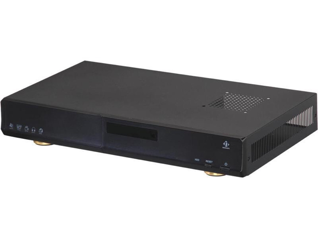
-An aluminum media center housing. Reef-pi all sensors, etc go in here.
-Ordered a second raspberry pi. And Phone batter backup. This attaches to display. Now when not charging this is mobile, connects to reef-pi via web server only.
-with the aluminum housing i can use rj45’s and bnc for every connection. Easier to work with cutouts than the full plastic of a project box.
- larger power supply can fit in the box. Will require a fan now but thats not really an expense. But will be able to power all probes from one supply.(with proper voltage regulation of course lol)
-fit flat under my dosing pumps.
-thinking of using the lcd screen on the media center to be controlled by a simple program that says hello and good bye (on/off). And power button to initiate shutdown and on. Open source is great for simple tasks lol.
-room for upgrades.
-Only power strip and display will not be inside the housing.
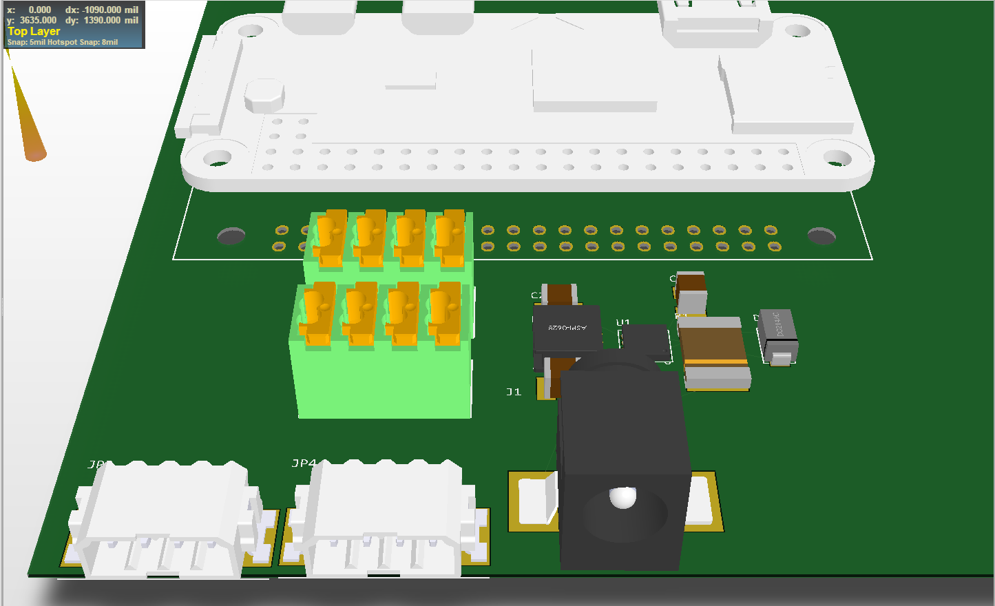
what the reef-pi is going in. Will post pictures of my build steps once i have all the parts. Using perfboards and single core wires for stability and t-cobbler to attach pi. No jumper wires.![]()
Love it.
What if we use hdmi connectors instead of rj45 ?
I would like to settle one audio jacks, barrel jacks, and hdmi if possible. Reason being they are universal (can get both panel mount and pcb mount connectors) and aesthetically more pleasing. BNC is kinda the only way to go for some probes, so no choice there,
Hey, did we get this sorted, if not. I should look into this. RPI based pwm drivers are not second class citizen. And it should work flawlessly , if you are still encountering issue (i.e. threshold are not solving the flashing), its likely a bug with on/off thing that we are doing in the reef-pi/rpi pwm code path. I would definitely address this before a public release.@Ranjib I've been investigating my "flashing" issue and had a question as i'm not used to working with GO. Could you share which methods are called by the cron, as i'm struggling to figure it out.
When manually setting the PWM values on the RPI I do not suffer with any flickering, I can also adjust the duty cycle up and down without any flickering. What i'd like to understand is how the cron is interacting with the RPI PWM interface, as it feels like PWM0 is being disabled/enabled when ever the cron runs. If I manually disable/enable PWM0 i'm able to replicate the "flash", this happens because my light's power supply doesn't receive a PWM signal so it defaults to 100% output. This is the data sheet for power supply i'm using, https://docs-emea.rs-online.com/webdocs/13ec/0900766b813eccfc.pdf
I went with hdmi because the number of pins are higher, and the breakout boards make it easy, if we go with pcb mount instead of panel mount then the wiring hassle is solved right?Hand terminating HDMI _cables_ is difficult. Connector shells are rare, the pitch is small. Hacking off an HDMI cable would then end up with a ton of wire nuts to actually connect to the intended wire.There are some odd Chinese HDMI to terminal block adapters, but we might as well just put terminal blocks right on the board then in smaller plugable increments, and less chance of error of connecting HDMI to the I/O port, or vice versa (since the RPi also has one).
Most of the sensors, outside of pH, are not using any standard connector so retaining full flexibility feels like the right strategy.
I like PicoLock connectors as well, but I would not suggest anyone hand-crimp the connector blades on them. It takes a special tool ($$$$, really Molex charges like $300 for a crimp tool) or a poor fit general purpose tool (still like $50).
Barrel is fine for power, as that is standardized.
Fascinating :-) I found the audio jacks are easiest and most minimal. They have exactly three pins that I need for building kessil controller or connecting temperature probe etc.Seconded - audio jack connectors are more of a pain to solder to or crimp to. Would you vote for RJ45 over a more conventional terminal block?
You work is really cool. Thank you for sharing this with us.Hi all,
I'm new here and I'm also bussy working on the harware.
Down here you will find a schema and pcb for mine. Basically it is four sollid state relais to drive 240V.
Also four connectors for four ds18b20 that are ordered.
![]()
![]()
It is ready and working well.. I did not make pictures yet. But they will be placed later.
Keep in mind that if you are going to use my schema, IT IS HIGH VOLTAGE and DANGEROUS for humans.
There are a lot of question that I have. I don't know go lang yet, and alo JSX I'm not familiar with. But my idea is to make a selection in the configuration that it is posible to choose between fahrenheit and celsius. It is pitty that it now converts the current response from the sensor to fahrenheit. When it only converts it's value when it shows it, it would be beter I think. But I don't know how to do this. Is there a good document that describes how the current reef-py software works? Is the database prebuilded, or is it build when first time reef-py is started? (build in the code)
So basically my question is, HELP ME getting started with learning JSX, GO, and all there is to devellop for the reef-py.
Regards,
Marc
We can also mount ds18b20 in to-92 packaging to sense the onboard heat. I think it will be a good thing to have as a general safety measure, since we are likely to have voltage regulators (for multiple output PSUs) and pwm converter (5v -> 10v or 25v using mosfets or tip120) which also have this risk.It is 3A fast fuse. Just to protect against shorting. So max 3A total (all 4). I will never drive than mutch. I used 16A triacs just because I still had them. Now, one is driving my 15W light. (15/240=62mA) Don't think you ever will notice any power dissipation in the triac. If you want to drive more power, you might want heatsinks. But TO220 can also dissipate without heatsink. I never did calculate it, but I have done a lot with triacs and from my experiance you need cooling on those if you drive more than about 3A for one triac that is switching 240V. You might always want to check after using a bit. (Kill the power first)
greetings.
I went with hdmi because the number of pins are higher, and the breakout boards make it easy, if we go with pcb mount instead of panel mount then the wiring hassle is solved right?
I am leaning on hdmi over rj45 becuase it has more pins, folks who wants 16 channel relays can use it.
I agree, if user confuse the hdmi connector, it will foo bar big time :-) . Thats a very good thought. I guess it was not obvious to me, as I am mostly using pi zero, and the mini-hdmi connector makes it less obvious. Keep us posted,To rehash my thinking:
Downside: everything is on one cable breakout dongle. Requires a dongle. Confusion with the HDMI port on a raspberry Pi will eventually cause some sad Pi, monitor, or base board.
Upside: As you said, single plug. It does make the actual base board smaller. If I make a female on both ends with a dongle with terminal blocks, a standard HDMI cable can be used to remote locate the actual signals. There are differential pairs that can be exploited to not make a mess of any analog signals. HDMI connectors are reflowable (unlike cheap terminal blocks). HDMI connectors are cheap.
I’m going to go with HDMI for now and backup to the push-in wire pluggable connectors.
I’m pretty cold on RJ45. Let’s consider that dead.
Thanks :)
The only thing I am still not sure about the HDMI route is if its safe for relay use. My understanding is hdmi specs limit current draw to 60ma, and most relays (mechanical or ssds) will draw 20ma per channel. So this is safe. But I think it will be nice to know how much current I can draw, anyway.I agree, if user confuse the hdmi connector, it will foo bar big time :) . Thats a very good thought. I guess it was not obvious to me, as I am mostly using pi zero, and the mini-hdmi connector makes it less obvious. Keep us posted,