Trying to understand the system

Users Who Are Viewing This Thread (Total: 1, Members: 0, Guests: 1)

Rototank

New Member
View Badges
Joined
Mar 15, 2021
Messages
13
Reaction score
41
Location
Charleston
Rating - 0%
0   0   0
Hi everyone, I am trying to figure out how to better understand the system.

Here is what I would like to do with my RODI, but not sure how to do it.

1- when level sensor 6 is triggered I would like the container to fill (by turning outlet 7 ON - have a solenoid)

2- when outlet 7 is ON I would also like outlet 8 to be ON for 120 seconds (solenoid to flush the membrane) the first time and then for 120 seconds every hour.

3- if voltage 1 (ADIN card) is above 2 I would like to turn off and prevent outlet 7 from turning ON.

@Lasse I know you have helped others with something similar, I hope you can give me a hand as well (I can't thank you enough for all you do for us GHL users!). I tried other configurations but with no success.
 
Last edited:

CEReefer

Well-Known Member
View Badges
Joined
Sep 7, 2019
Messages
589
Reaction score
329
Rating - 0%
0   0   0
Maybe something with PL would work, not sure how you can use the V1 from the ADIN card to avoid a switch channel from turning ON.
 

Lasse

10K Club member
View Badges
Joined
Mar 20, 2016
Messages
10,863
Reaction score
29,841
Location
Källarliden 14 D Bohus, Sweden
Rating - 0%
0   0   0
I´m sorry - I forget

The tricky one - for me is the hourly flush when solenoid 7 is on

But I´ll start with a question - sensor 6 should turn outlet 7 on - but what in normal cases should turn i off - the 2 V signal?

Sincerely Lasse
 
OP
OP
Rototank

Rototank

New Member
View Badges
Joined
Mar 15, 2021
Messages
13
Reaction score
41
Location
Charleston
Rating - 0%
0   0   0
I´m sorry - a lot of work - also during evenings - I´ll be back

Sincerely Lasse
No worries, I totally understand.
I´m sorry - I forget

The tricky one - for me is the hourly flush when solenoid 7 is on

But I´ll start with a question - sensor 6 should turn outlet 7 on - but what in normal cases should turn i off - the 2 V signal?

Sincerely Lasse

No worries, I understand everyone is busy, thank you for helping everyone!

To answer your question, yes. Sensor 6 turns switch 1 ON, Sensor 5 will turn it OFF. But if the Voltage goes above 2 the switch will turn OFF.

Sensor 5 is the max level in the RODI container.
Sensor 6 is the low level in the RODI container.
The 2-10 volts (it’s 2-10 instead of 0-10, because it’s converted from a 4-20mA signal generator) is TDS meter, if it goes above 2 the TDS is above 0.


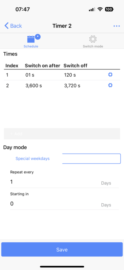
For the flush, would it work if we use PL for the first task (for example PL1) and I create PL2 with a cyclic timer on at 0sec off at 120 and then on at 3600 and off at 3720 sec AND PL1?

attached a screenshot of the timer
 

Attachments

  • 855CF1B5-B618-4803-AE2D-B79DF4B6C91F.png
    855CF1B5-B618-4803-AE2D-B79DF4B6C91F.png
    63.3 KB · Views: 28

Lasse

10K Club member
View Badges
Joined
Mar 20, 2016
Messages
10,863
Reaction score
29,841
Location
Källarliden 14 D Bohus, Sweden
Rating - 0%
0   0   0
Can you send a screenshot of your level control circuit? And the description (screenshot) of the present programming of outlet 7 - the outlet that manage the RO solenoid

Sincerely Lasse
 
OP
OP
Rototank

Rototank

New Member
View Badges
Joined
Mar 15, 2021
Messages
13
Reaction score
41
Location
Charleston
Rating - 0%
0   0   0
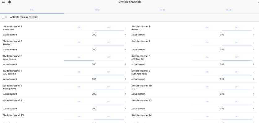
I screenshotted it all. Switch 7 is the RODI top off (motorized ball valve) and switch 8 is the autoflush solenoid
 

Attachments

  • Screen Shot 2022-12-01 at 15.24.59.png
    Screen Shot 2022-12-01 at 15.24.59.png
    41.7 KB · Views: 28
  • Screen Shot 2022-12-01 at 15.24.38.png
    Screen Shot 2022-12-01 at 15.24.38.png
    48.6 KB · Views: 26
  • Screen Shot 2022-12-01 at 15.24.20.png
    Screen Shot 2022-12-01 at 15.24.20.png
    22.2 KB · Views: 22
  • Screen Shot 2022-12-01 at 15.22.39.png
    Screen Shot 2022-12-01 at 15.22.39.png
    80 KB · Views: 18
  • Screen Shot 2022-12-01 at 15.22.08.png
    Screen Shot 2022-12-01 at 15.22.08.png
    21.3 KB · Views: 17

Lasse

10K Club member
View Badges
Joined
Mar 20, 2016
Messages
10,863
Reaction score
29,841
Location
Källarliden 14 D Bohus, Sweden
Rating - 0%
0   0   0
What I see here is that you only have a 1 sensor control (sensor 6) at your control channel 3. The switch off (sensor 5) seems not to be in charge. I´ll setting up a test P4 this morning (your night) - coming back later on

Sincerely Lasse
 

Lasse

10K Club member
View Badges
Joined
Mar 20, 2016
Messages
10,863
Reaction score
29,841
Location
Källarliden 14 D Bohus, Sweden
Rating - 0%
0   0   0
Note - you have to test this by yourself and be sure it works- I have not tested all things and I can have done errors.

First report - I use the min-max function. In my case I use sensor 1 and 2. 2 is the upper and 1 is the lower - in your case you should use sensorindex 5 as sensor 1 (upper) and sensorindex 6 as sensor 2 (lower) I use index 2 and 1. sensorindex - black marking. I also assume that your max time should be 3 hours. If you want - you can set reset error automatic. Its works like this IF all is filled up - both sensors show a

1669969718741.png


Its works like this If all is filled up - both sensors show a v mark

1669970052428.png

and no filling
1669970284021.png


ATO is filling up the DT - and the RO containers water level is going down - the upper sensor will be activated

1669970419141.png


Still no filling

1669970461796.png


The RO container is empty and the lower sensor is activated too

1669970575849.png


Now it is able to activate your valve and the RO will be filled into the container

1669970673792.png


It slowly fill up - the lower sensor is deactivated - but the filling goes on

1669970776933.png

1669970814172.png


The container is filled up to the upper sensor - its deactivated and the filling is no more

1669970939072.png

1669970980796.png


Now is the first part for your ball valve ready . In order to add the function of shout of if the rodi if your TDS is to high. I do a separate post

Sincerely Lasse
 

Lasse

10K Club member
View Badges
Joined
Mar 20, 2016
Messages
10,863
Reaction score
29,841
Location
Källarliden 14 D Bohus, Sweden
Rating - 0%
0   0   0
Your voltage - yes maybe its possible to use the PL you create

1669972267555.png

and knit it to outlet 7

1669972391301.png


But I believe that you need to do these settings

1669974740458.png


I can´t test this because my ad in card is in my online computer and I will get trouble if I test it in a sharp way

If this not work - you can test with these settings

1669972954821.png


and use a Pl that's says. Knit it to outlet 7

1669973347717.png


Only to have the initial flush - its easy - make a PL like this and knit it to outlet 8

1669973749333.png


If you want a flush every hour too - it can be complicated because you may not want this if the voltage had shout the whole operation down

Sincerely Lasse
 
Last edited:

Being sticky and staying connected: Have you used any reef-safe glue?

  • I have used reef safe glue.

    Votes: 84 87.5%
  • I haven’t used reef safe glue, but plan to in the future.

    Votes: 6 6.3%
  • I have no interest in using reef safe glue.

    Votes: 3 3.1%
  • Other.

    Votes: 3 3.1%
Back
Top